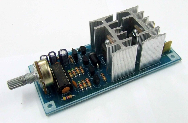
How to Make a Speed Controller for a Dc Motor

DC motors run on direct current as opposed to the alternating current present in our home and office electricity system. So, for a DC motor to work on alternating current, an AC to DC converter is required. The conversion is provided by a rectifier circuit which consists of 4 diodes connected in series with a source of alternating power. Since diodes conduct electricity in one direction only, providing two separate paths for the electric current to travel rectifies or converts the electricity from alternating to direct form.
Things Required:
– Strong cardboard
– Solution tape
– Computer software(Proteus) and a printer
– Wire strippers
Instructions
-
1
First of all you will have to make a rectifier circuit for the conversion of alternating current into direct current. Place 4 diodes in a way as to make a mesh circuit, such that one strip of wire connects two diodes and is used for conducting the current in one direction, where as the other strip of wire transfers current when the alternating current goes through its negative cycle, hence keeping the flow of electricity in one direction.
-
2
Transformer chosen in the rectifier circuit depends on the power requirements of the DC motor. If your DC motor requires 12 volts for its running, choose an 18 volts transformer and then use them to produce 12 volts of direct current in the rectifier circuit.
-
3
The speed of the DC motor can either be controlled manually by a variable resistor or by generating a pulse wave modulation through a programmable controller and feeding it to the DC motor.
The first option is pretty simple; all you have to do is to connect a rheostat in series with the output of the rectifier circuit and feed it to the DC motor. -
4
You will now be able to adjust the speed of the motor by turning the knob of the rheostat - turning it changes the variable resistance in the coil. As the variable resistance is acting as a voltage divider, changing the resistance changes the voltage drop across the terminals of the DC motor, which in turn changes the speed of the motor.
-
5
Another way to go about this is to use an embedded micro controller in your project. There are different micro controllers available easily in the market such as the PIC Micro controller or the popular 8051 series. Choose an appropriate controller and generate PWM (Pulse Wave Modulation) on one of its terminals, and use PWM to control the speed of the motor.


